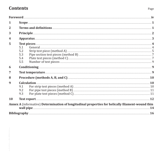
ISO 8513:2014 pdf download.Plastics piping systems — Glass- reinforced thermosetting plastics (GRP) pipes — Test methods for the determination of the apparent initial longitudinal tensile strength
This International Standard specifies three test methods for determining the longitudinal tensile properties of glass-reinforced thermosetting plastics (GRP) pipes. The properties which can be determined are
— the longitudinal tensile strength and
— the percentage ultimate elongation.
Method A uses, for the test piece(s), a longitudinal strip cut from a pipe.
Method B uses a specified length of the full cross-section of the pipe.
Method C uses a notched plate cut from a pipe wall section.
Method A is applicable to pipes with a nominal size of DN 50 or greater with circumferentially wound filaments, with or without chopped glass and/or woven rovings and/or fillers, and to centrifugally cast pipes. It is applicable to pipes with helically wound filaments with a nominal size of DN 200 or greater.
Method B is applicable to all types of GRP pipe. It is usually used for pipes with a nominal size up to and including DN 150.
Method C is primarily intended for use for helically wound pipes with a winding angle other than approximately 90°. This method can also be used for other types of pipe.
Results from one method are not necessarily equal to the results derived from any of the alternative methods. However, all methods have equal validity.
Annex A describes additional considerations for method B that have been found useful for the testing of thin-walled helically wound pipes and can be used to supplement the basic text.
NOTE This International test method does not address the determination of longitudinal tensile modulus.
Due to the multi-layer construction of many GRP pipes, the accurate measurement of strain, necessary for modulus determination, can be very difficult. If it is desired to determine longitudinal modulus, it is recommended that ISO 527-4 and/or ISO 527-5 be consulted.
2 Terms and definitions
For the purposes of this document, the following terms and definitions apply.
2.1 helical wound
sometimes called cross wound, refers to filament-wound pipes made with a balanced winding angle
2.2 longitudinal tensile strength
maximum tensile force in the longitudinal direction per unit mean circumference at failure (the
subscripts A, B, and C denote the method of test used)
Note 1 to entry: It is expressed in newtons per millimetre of the circumference (N/mm).
2.3 mean circumference
circumference corresponding to the mean diameter multiplied by π (π ≈ 3,141 6)
Note 1 to entry: It is expressed in millimetres.
2.4 mean diameter
d m diameter of the circle corresponding with the middle of the pipe wall cross-section Note 1 to entry: It is given by any of the following:
a) the average of the external diameter of the pipe minus the average of the wall thickness;
b) the external circumference of the pipe divided by π (π approximately 3,141 6) minus the average of the wall thickness;
c) the average of the internal diameter of the pipe plus the average of the wall thickness.
Note 2 to entry: It is expressed in millimetres.
2.5 ultimate longitudinal tensile stress
σ L,ULT
maximum longitudinal tensile force per unit cross-sectional area at failure
Note 1 to entry: It is expressed in newtons per square millimetre (N/mm).
2.6 ultimate elongation
ε L elongation coincident with the ultimate longitudinal tensile stress
Note 1 to entry: For the purposes of this International Standard, the measurement of elongation is limited to measurement of the movement of the tensile testing machine cross-heads.
Note 2 to entry: It is expressed as a percentage of an initial gauge length or free length of a test piece.
3 Principle
Test pieces comprising either strips cut longitudinally from a pipe wall segment (method A), a specified length of pipe (method B), or a notched plate cut from a pipe wall section (method C) are subjected to extension in the longitudinal direction at a constant speed such that fracture occurs within a specified time.
The tensile properties are determined using the initial dimensions of the test piece, the tensile force, and the cross-head movement.ISO 8513 pdf download.ISO 8513 pdf download
