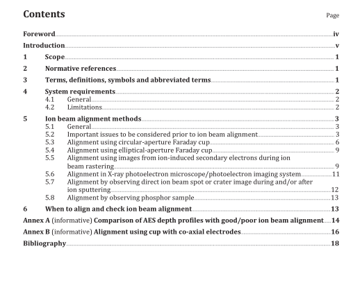
BS ISO 16531:2013 pdf download.Surface chemical analysis — Depth profiling — Methods for ion beam alignment and the associated measurement of current or current density for depth profiling in AES and XPS
4 System requirements
4.1 General This International Standard is applicable to the focusable ion gun for sputtering with inert gases that is usually supplied with most of AES and XPS instruments or available from after market suppliers. The beam size or raster area of the ion beam shall be larger than and uniform over the analysis area. Seven alternative methods of ion beam alignment are described that require the equipment to have provision for the measurement of the ion current, or for detecting excited secondary signals, or an optical microscope aligned at the analytical point. Depending on the equipment available, measurements of increasing sophistication may be made. The methods for measuring the ion beam current involve measurement by a circular-aperture Faraday cup, elliptical-aperture Faraday cup or a co-axial electrode cup. The methods involving the excited secondary signals are categorized by ion/electron-induced secondary electrons or emitted photons that are detected with a secondary electron detector, an optical microscope or a phosphor screen. To conduct the relevant surface analysis, the electron energy analyser, the analysis probe beam and the ion beam need to be focused and aligned correctly on the same analysis point or area to be analysed. To apply this International Standard, the electron energy analyser and the analysis probe beam shall already be aligned to the optimum position using the manufacturer’s or in house documented procedure.
4.2 Limitations
This International Standard is an important part of the setting up of depth profiling generally; nevertheless, depending on the material of the sample and its structure, there are several depth profiling procedures that may be applied to achieve the best depth resolution, not all of which are aided by this International Standard. Some of the most popular procedures are
a) ion bombardment of fixed position samples at angles of incidence in the range of 0°–60° with respect to the surface normal,
b) ion bombardment at grazing angles of incidence,
c) sample rotation during ion bombardment,
d) simultaneous ion bombardment applying two ion guns, and
e) sample rotation and grazing angle of incidence for ion bombardment.
This International Standard will assist in the use of procedure a). Some aspects may relate to the other procedures but further considerations may be required that are not necessarily included in this International Standard.
5 Ion beam alignment methods
5.1 General
This International Standard describes not all but seven simple methods for ion beam alignment, easily applied. These methods and a summary of their advantages are set out in Table 1. Also indicated are which methods are best for ion beam current or current density measurement. Each method has different advantages and requires different instrumental capabilities. The analyst needs to select the method based on requirements and equipment capabilities. Some issues depend on the raster size of the ion beam. A small raster is good, since little material is consumed or sputter deposited in the spectrometer. Additionally, for industrial samples, the material to be profiled may only occupy a small area. A very small raster is possible in AES where the electron beam is small and some users may deliberately use higher ion beam energies where ion beams tend to be better focused to obtain small sputtered areas with a faster sputtering rate. In these cases, and for systems with small-area XPS analysis, particular care needs to be taken with alignment. For broader ion beams, such as for some XPS instruments, the alignment accuracy may be more relaxed. If more than one method is suitable, tests with each will show which is most convenient for the sputtering conditions intended.BS ISO 16531 pdf download.BS ISO 16531-2013 pdf download
