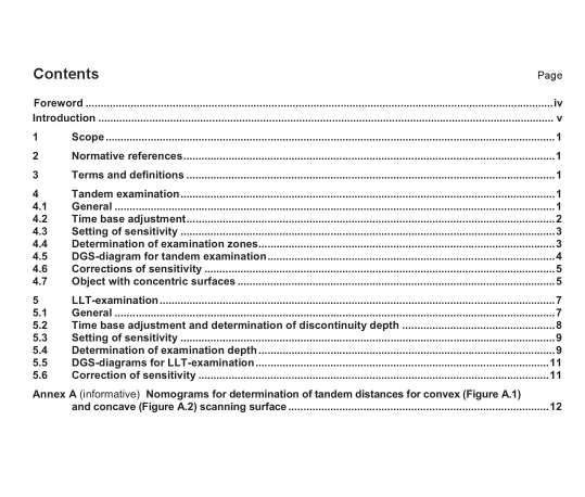
EN ISO 16826:2014 pdf download.Non-destructive testing – Ultrasonic testing – Examination for discontinuities perpendicular to the surface (ISO 16826:2012)
This International Standard defines the principles for tandem- and longitudinal-longitudinal-transverse (LLT) wave examination for the detection of discontinuities perpendicular to the surface.
The general principles required for the ultrasonic examination of industrial products are described in ISO 16810. A list of symbols and equations is given in ISO 16811.
The tandem- or LLT-examination should be used for the detection of planar discontinuities with distance to the surface greater than 15 mm. This International Standard has been prepared for the examination of metallic materials with a thickness between 40 mm and 500 mm with parallel or concentric surfaces. It can, however, be used for other materials and smaller thickness provided special measures are taken.
2 Normative references
The following referenced documents are indispensable for the application of this document. For dated references, only the edition cited applies. For undated references, the latest edition of the referenced document (including any amendments) applies.
ISO 5577, Non-destructive testing — Ultrasonic inspection — Vocabulary
ISO 16810, Non-destructive testing — Ultrasonic testing — General principles
ISO 16811, Non-destructive testing — Ultrasonic testing — Sensitivity and range setting
3 Terms and definitions
For the purposes of this document, the terms and definitions given in ISO 5577 and EN 1330-4 apply.
4 Tandem examination
4.1 General
The examination is normally carried out using two similar 45° angle probes, one probe operating as the transmitter and the other probe as receiver. For wall thicknesses greater than approximately 160 mm, probeswith different transducer sizes are preferred in order to ensure approximately the same beam diameters in the examination zone.
The use of probe angles other than 45° may be necessary to comply with particular geometrical conditions.
Probe angles that give rise to mode conversions shall be avoided.
The probes are located in a line with their acoustic axis in the same direction. In this way the sound beam from the rear probe will, after reflection from the opposite surface, intersect the sound beam from the front probe at the centre of the examination zone. Figure 1 shows the relationship between the spacing of the probes (y) and the examination depth of the crosspoint (t m ) and the height of the examination zone (t z ).
Scanning shall be performed in either of the following ways:
⎯ both probes are moved along the surfaces with a fixed distance (y).
In this way only one examination zone is examined at a time, and the scanning shall be repeated with different probe distance until the complete examination volume has been examined;
⎯ both probes are moved simultaneously, such that the sum of their distances from the required plane of intersection, e.g. the vertical weld axis, remains constant, thereby scanning the full object thickness in one continuous movement.
4.2 Time base adjustment
Basically all relevant echoes will appear at the same sound path distance, which corresponds to the V-path.
Therefore, the adjustment of the time base is not important. It is, however, recommended that the echo from the V-path is located at a fixed position e.g. eight scale divisions.
4.3 Setting of sensitivity
The setting of sensitivity can be performed using the following reflectors:
⎯ opposite surface, where the V-path echo is used as backwall echo;
⎯ disk-shaped reflectors perpendicular to the scanning surface (flat-bottomed holes). The reflectors shall
be located at the intersection of the beam axes;
⎯ side drilled holes located at the intersection of the beams and at the borders of the examination zones.
4.4 Determination of examination zones
The division into equally sized examination zones ensures that the sensitivity throughout the thickness does not fall below a certain level. The height of the examination zones is calculated so that the sensitivity at the edges of the examination zones is not more than 6 dB below the sensitivity in the intersection point of the beam axes, see Figure 2.EN ISO 16826 pdf download.EN ISO 16826 pdf download
